Kraków 2025-02-24
First electric locomotives in Poland at PKP.

In the chapter – Electric traction in Poland in PKP. 2021. – we discussed why we have a 3 kV DC power supply in PKP. After the change of power in Poland, on December 13, 2023, the new government abolished the CPK (Central Communication Port) program. At the same time, the program of electrification of new routes with 25 kV 50 Hz electricity was abolished. As a result, Polska Kolej and the entire Polish transport will face a regression in development.
Let us recall that in 2023, experts and experts on the subject made the following announcements. – “It is almost certain that the new railway lines to be built as part of the so-called CPK railway component will be electrified in the 25 kV AC system.” – This will not happen. At least not for the coming years. The reason is the priorities of the new/old government of the Volksdeutsche, communists and freemasons. And the loss of independence is becoming more and more real. According to the unchanged opinion – “Different power supply systems are one of the most important barriers to the interoperability of railways in Europe.” The voltage of 3 kV DC used in Poland is only partially used in the traction network of the Czech Republic, Slovakia and Ukraine by our neighbours. Generally, countries to the west of Poland use the 25 kV AC system, and for example Austria and Switzerland use 15 kV AC current. The voltage of 3 kV DC can only be found in Belgium and Italy. We wrote about other advantages of alternating current (AC) in the aforementioned article. But we also wrote about its disadvantages. However, we must remind you that with a current of 3k DC, it is possible to travel by train at a speed of 250 km/h, which is currently sufficient.
The history of electric locomotives.
The first electric locomotives were equipped with two large and heavy electric motors. That is why they were placed in the locomotive body. The transfer of drives to the wheels was a reproduction of that used in steam locomotives. Blind shafts and trusses were used. These were not primitive solutions, but proven and reliable solutions. Already at this stage, a number of advantages of electric locomotives were noticed, in relation to steam locomotives. An excellent place where electric locomotives showed their advantages were mountain trails that ran through tunnels. In Switzerland, the tunnel on the Simplon Pass was used for tests. These tests brought success. As early as 1895, in the USA near Baltimore, trains were pulled through a 4 km tunnel using electric locomotives. This was the first case of using electric locomotives on main lines in the USA. Also in Scandinavia, on the raw materials export line, three-section electric locomotives with a truss system were used, in the 1’D+D+D1’ axle arrangement. In addition, these locomotives operated in Arctic conditions. In 1920, Switzerland began electrification of railway lines. Sweden and Austria followed. However, widespread electrification began after World War II.
Attempts were made to replace the crankshaft drive system with other gears. Progress in the design of electric engines increased their power, while reducing their size and weight. As a result, it was possible to use a tram engine suspension system, which is still used today. Although not always. The tram system (by the nose) causes half of the electric engine mass to rest on the axle and allows the locomotive to run smoothly at speeds of up to 160-200 km/h. At the same time, the use of rolling axles or rolling bogies was abandoned. The axle arrangement of electric locomotives was adopted; Co’Co’, Bo’Bo’Bo’, Bo’Bo’. The latter is the most popular. The abandonment of trusses freed locomotives from their greatest drawback: unbalanced masses and the associated adverse effect on the track.
This does not mean, however, that other experimental solutions were not sought. For example, vertically placed engines or engines mounted entirely on the axle. And an engine placed in the box and driving the bogie axles via a cardan shaft. This solution was adopted.
The method of supplying electric power to the locomotive was also solved. Initially, a whip was used, at the end of which there was a grooved or roller slide. Later, there were lyre-shaped collectors. The most popular proved to be a current collector in the form of a pantograph, which contacts the contact wire suspended above the track. Current collection from the third rail, which is mainly used in the metro, was also adopted.
In the 1920s, a system consisting of three overhead wires for three-phase current was briefly developed. These wires were placed on the side of the tracks on poles, and the electric locomotive had three current collectors. This was a troublesome solution. This system was temporarily used on the Sand Railway in Poland. Currently, on the lignite mine railway near Konin, LEW EL2 electric locomotives have an additional side current collector.
The first train in Poland powered by electricity was launched in 1927, on the Electric Commuter Railway line from Warsaw to Grodzisk Mazowiecki, and the first on the PKP line in 1936, on the route; Otwock – Warsaw – Pruszków. The way for the electrification of PKP was paved by the pioneering work of the team of Professor Roman Podoski (1873-1954), who was a member of the board and president of the Warsaw Branch of SEP (Association of Polish Electricians). Already in the 1920s, a decision was made to electrify the railways in Poland with 3 kV DC current. The adopted technical solution turned out to be correct and is still used today. 3 kV DC current is well suited for servicing both heavy freight trains and fast passenger trains.
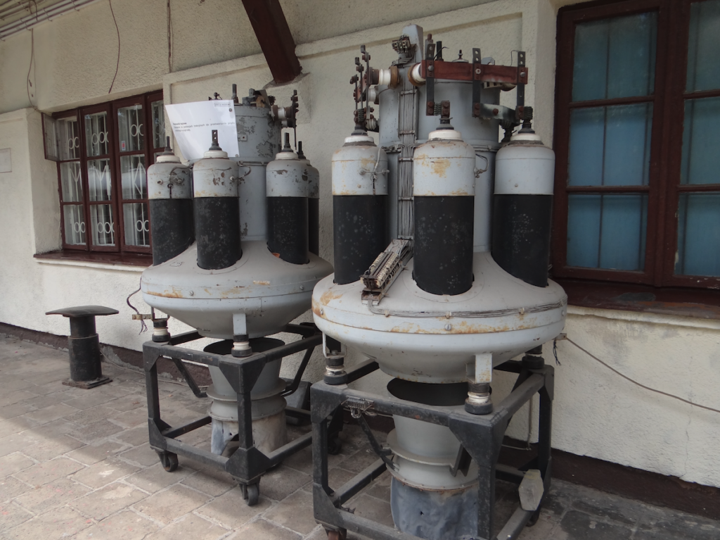
It was of great importance to build a good mercury rectifier. Rectifiers of this type are used in traction substations, where alternating current from the general power grid is converted to direct current (3 kV DC) and directly fed to a given section of railway overhead traction. One of the advantages of this system is that there is no need to build separate power plants for the railway.
The first electric locomotives in Poland.
On August 2, 1933, in London, a delegation of the Polish State Railways concluded an agreement with the British companies English Electric and Metropolitan-Vickers for the electrification of the cross-city line and suburban routes from Warsaw to Otwock and Pruszków. The agreement provided for the delivery of two EL.100 electric locomotives and electrical equipment for vehicles to be manufactured in Poland, i.e. EL.100 and EL.200 electric locomotives and three-car suburban multiple units EZT E91000 and E92000.
The first two EL.100 electric locomotives were manufactured in 1934 at the Metropolitan-Vickers plant in Manchester and then transported to the port of Gdynia on board the Polish freighter “Lublin”. After being put on the tracks, the EL.100 locomotives were transported to Warsaw using a steam locomotive.
The next four EL.100 locomotives for PKP were to be manufactured in Poland, using electrical equipment components supplied by the British. The production of these locomotives was commissioned to the First Locomotive Factory in Chrzanów, where the bodies and mechanical parts of the locomotives were manufactured. The electrical part supplied by the English Electric plant was installed in cooperation with British engineers. The electric locomotives built in 1935-1936 were given the factory designation 1EL and factory numbers from 634 to 637, and series designations from EL.103 to EL.106. The cost of building one EL.100 locomotive was PLN 705,000, and the locomotives were covered by a one-year manufacturer’s warranty.
In September 1936, during the Exhibition of the Metal, Electrical and Radio Industry held at Pole Mokotowskie in Warsaw, the EL.103 electric locomotive was presented as the first electric locomotive produced in Poland.
In the first quarter of 1939, four additional sets of electrical equipment were ordered in Great Britain for the construction of subsequent vehicles from this series. The shipment arrived in August 1939 at the port of Gdynia, but then the Germanic and Muscovite brothers jointly attacked the Republic of Poland. The electrical components were lost.
Electric locomotive EL.100.
The electric locomotive EL.100 already resembled today’s electric locomotives. The body of the EL.100 series locomotives is a rigid frame made of sections covered with steel sheets. Removable parts of the skin were screwed together, and the remaining panels were riveted. This design allowed easy access to the electrical components. The box was divided into five parts: a central high-voltage part, two auxiliary parts and control cabins located at both ends of the box. Inside, there is a corridor that connected both cabins. Counting from cabin No. 1, there were five windows on the right side of the box, three of which were non-opening and two with blinds, and ten vents. On the other side (from the corridor side), the manufacturer placed two non-opening windows, one sliding and four with blinds, and two vents. The control cabins were accessed through four pairs of doors, two on each side of the box. The front walls were fitted with non-opening windows: a single pane of glass was fitted on the driver’s assistant’s side, and an electrically heated double pane on the driver’s side. Windshield wipers were fitted: pneumatically powered on the driver’s side, and manually operated on the assistant’s side. Three reflectors were fitted in each locomotive’s front. A pneumatic siren was fitted on top. A folding ladder was fitted in the middle of the front wall by cabin no. 1, allowing access to the roof of the locomotive. Unfolding the ladder automatically folded the pantographs. A 2.4 mm thick sheet metal was laid on the roof. The sheets above the electrical parts were fastened with screws for dismantling. The frame was made of beams made of steel profiles. The floor was riveted to the frame. Cast iron pins were fitted to the frame for connection with the bogies.
The driver’s cabin was fitted with a controller with 35 positions and a reversing switch. There were also clocks; ammeters and voltmeters. There was a switchboard, locomotive and main brake taps, a speedometer and brake system manometers. In front of the assistant was a handbrake wheel and an electric stove. There was also a tool cabinet. Drivers sat on swivel stools. In the rear wall there was a door to the corridor, a fuse and switch box, a fire extinguisher, an electric heater, an additional reclining seat. The walls were lined with wood, and the floor was additionally linoleum.
In the engine compartment there were: converters with fans, compressed air tanks, two compressors, an iron-nickel battery. There was also a clothes locker. In the high-voltage compartment there were contactors, electropneumatic and auxiliary relays, traction motor switches, an energy consumption meter, a reversing switch, starting resistances cooled by air from fans. Access to the compartment was possible after disconnecting the power supply and lowering the pantographs, and observation of the electrics could also be carried out without having to open the door through a window located in the compartment wall. There were also hatches in the floor of the engine room allowing access to the traction motors.
The locomotive was equipped with a Bo’Bo’ axle system. The frame of the bogies was made of steel angles and sheets riveted to them. Scrapers were attached to the external end carriages, and above them a screw coupling and two buffers. The bare wheels have 12 spokes and rims are put on. The wheel sets operate on slide bearings with fork guidance. One axle from each bogie axle is connected to the speedometer. The engines were mounted in a tram manner. The suspension is single-stage, consisting of leaf springs. The electric locomotives manufactured in Poland had additional coil springs between the springs and axle boxes, which softened the suspension a bit and improved driving characteristics. Sanders were installed.
MV185 engines, manufactured by Metropolitan-Vickers. The 1500 V engines were permanently connected in pairs in series. One engine produced 338 kW of continuous power at 930 rpm. The engine weighed 4,890 kg. The transmission was single-stage with a ratio of 69:22, with straight teeth. The service life of the transmission was 300,000 km. The EL.100 timing gear was a resistance, manual with electro-pneumatic control. The locomotives did not have multiple control. Current collection from the traction network was provided by two scissor pantographs. Pneumatic lifting and lowering of the current collectors was possible thanks to valves in the driver’s cabs.
In 1936, night test runs and driver training began on the electrified sections of the Warsaw Railway Junction. From 15 December 1936 (the official opening date of the electrified Pruszków – Warsaw – Otwock line), tests were also carried out with suburban trains on the newly electrified section from Warsaw East to Pruszków. In October 1937, EL.100 electric locomotives were assigned to pull suburban trains to Otwock, Żyrardów and Mińsk Mazowiecki. Part of the shunting work on the cross-city line was taken over by light shunting locomotives of the EL.200 series. This division of tasks lasted until the outbreak of World War II, i.e. the invasion of Poland by the Germanic and Muscovite brothers. After the outbreak of World War II, the EL.103 locomotive was destroyed, and the remaining ones were taken over by the Germans. The locomotives were changed to the E100 series (numbers E101 to E106). By 1945, only the electric locomotive EL.106 (Germanic designation E106) survived and worked normally in passenger traffic, and was stationed in the Łódź Olechów locomotive depot. In 1951, the locomotive’s designation was changed to E01-01, and in 1959, to EP01-01. Some of the locomotives were taken to the Germans and then scrapped. The fate of the entire series is as follows: EL.101 – damaged in 1944. Scrapped at Olszynka Grochowska after 1957. EL.102 – taken to the Germans, scrapped in Desching after 1958. EL.103 – destroyed in September 1939. EL.104 – exported to the Germans, scrapped in Desching after 1958. EL.105 – exported to the Germans, scrapped in Desching after 1958. EL.106 – withdrawn in 1964, scrapped at MD Łódź Olechów in 1968.
Electric locomotive EL.200.
In the interwar period, Polish industry, in cooperation with British specialists, launched the production of another electric locomotive type EL. 200, which was intended for shunting work and pulling passenger trains through the tunnel of the Warsaw cross-city line.
EL.200 is a series of four electric locomotives manufactured in the H. Cegielski plant in Poznań in 1937, for PKP. All locomotives were directed to service the Warsaw Railway Junction. Three copies were destroyed as a result of the attack of the Germanic brothers and Muscovites on Poland in September 1939. The fourth locomotive worked for the German occupiers until 1944, when it was damaged and was scrapped in 1958.
The locomotive has a Bo’Bo’ axle arrangement. Service weight 62,300 kg. Length 13.56 m. Width 2.86 m. Height 4.48 m. Wheel diameter 1.00 m. Number of engines 4. Engine type PK601. Power supply 3 kV DC. Continuous power 432 kW. Maximum tractive effort 99.8 kN. Gear ratio 74:21. Design speed 100 km/h. Axle load 15,600 kg. Westinghouse brake system.
In Poznań, the HCP factory built EL.200 locomotives without electrical equipment. These were vehicles with numbers; 342, 343, 344, 345. The locomotives were transported to Warsaw to the Lilpop, Rau and Loewenstein factory. Here, with the help of British engineers, the electrical equipment was installed. The locomotives received the series designations EL.201, EL.202, EL.203, EL.204.
The body structure is made of welded steel profiles and covered with sheets that are riveted or screwed. Screwed panels are used for service work. The end carriages are an integral part of the body, where screw couplers and buffers are mounted. To increase the weight of the locomotive, ballast in the form of reinforced concrete slabs weighing 6,000 kg was installed. The bogies are connected to the body by torsion pins. The bogies are the same as those mounted in the E-91 series EZT. The bogies use leaf springs and spiral springs, and the wheel sets are guided by forks. The engines are suspended in a tram-like manner. The gears are with helical teeth with a ratio of 74:21.
The EL.204 series locomotive (production number 345) was equipped with an electric steam boiler to heat the passenger cars. It was the first electric locomotive in the world with such heating.
In 1937, all 4 locomotives were sent to work between stations; Warsaw West – Warsaw East. On September 1, 1939, the Germanic brothers and the Muscovites attacked Poland and during a bombing raid on September 4, 1939, the locomotives EL.201, EL.202, EL.204 were destroyed. Locomotive EL.203 was put into service for the occupiers and worked until 1944, when it was damaged. After the war, it was not repaired, like locomotive EL.101. Locomotive EL.203 was a wreck in the Warsaw Grochów locomotive depot until 1958, when it was scrapped. The locomotive did not receive a post-war designation in PKP.
Electric locomotive EP02.
In Poland, the situation after World War II was bad. Poland was taken over by the communists and dependent on Moscow. It was difficult to rebuild the Polish railway industry, and the reconstruction of the Warsaw Railway Junction in particular was slow.
A statement by one of the Polish communists has been preserved, concerning the electrification of the railways: “Despite the enormous successes and superiority of Soviet electrification technologies, our big brother, for now, cannot help in the reconstruction of the Warsaw railway junction, because he has a lot to do at home.” This position of Moscow allowed Poland to establish cooperation with the UK and Sweden.
After World War II, the devastated country struggled to rise from the ruins. In Poland, there was only one electric locomotive, EL.106 (EP01), which worked and was withdrawn in 1964 and scrapped in MD Łódź Olechów in 1968. And before World War II, we had 10 electric locomotives (EL.100, EL.200), not counting EZTs.
The concept of purchasing and building a new series of electric locomotives was developed by the Central Design Office of the Railway Rolling Stock Industry (CBKPTK). In 1951, eight ASEA electric locomotives were purchased in Sweden, which were designated by PKP as the EP03 type.
In 1949, industrial cooperation with England was renewed and an agreement was signed with the “Contractors Committee for the Electrification of Polish Railways” representing the English industry. A contract was concluded for the delivery of MV 185 R traction motors and other electrical equipment. These were devices of the class used before the war in the EP01 electric locomotive.
In 1951, documentation for the new EP02 locomotive was developed at the Central Design Office of the Rolling Stock Industry in Poznań. The design included many modern design solutions that were not available in the interwar period. The design of the body and side frame was changed compared to its predecessors. The sheets were joined by welding instead of riveting. Headframes were installed, and on them the traction element and buffers. The body outline is more streamlined. The bogies have a lighter, welded construction with a shorter wheelbase, which ensured better cooperation with the track. The wheel sets were supported on double-row rolling bearings.
Production was undertaken at the PaFaWag plant in Wrocław, and the factory designation was given type 1E, and then changed to E110. The electrical equipment was purchased in England. The first EP02 locomotive was built in August 1953. The locomotive was sent for tests on electrified sections around Warsaw.
The first six locomotives were entered into PKP’s inventory in 1954, the seventh copy was introduced into service in 1956, and the last, eighth in 1957. The locomotives had factory designations from E110 to E117. The designation in PKP was the E02 series, and in 1960, it was changed to the EP02 series. The locomotive numbers were assigned from EP02-01 to EP02-08.
The first EP02 series locomotives began service in the Warszawa Zachodnia locomotive depot in Ochota and began servicing trains on the Warsaw-Katowice, Warsaw-Łódź, Łódź-Gliwice, Warsaw-Kutno routes. In 1958, the locomotives were transferred to the Łódź Olechów locomotive depot. In 1969, the locomotives were moved to the Dębica locomotive shed in DOKP Kraków. The locomotives serviced passenger trains on the Kraków–Przemyśl route.
During operation, the EP02 locomotives were modernized, adapting them to electric heating of the wagon trains. In 1959, “Czuwak” was installed in the locomotives, and in the 1960s, SHP devices were installed.
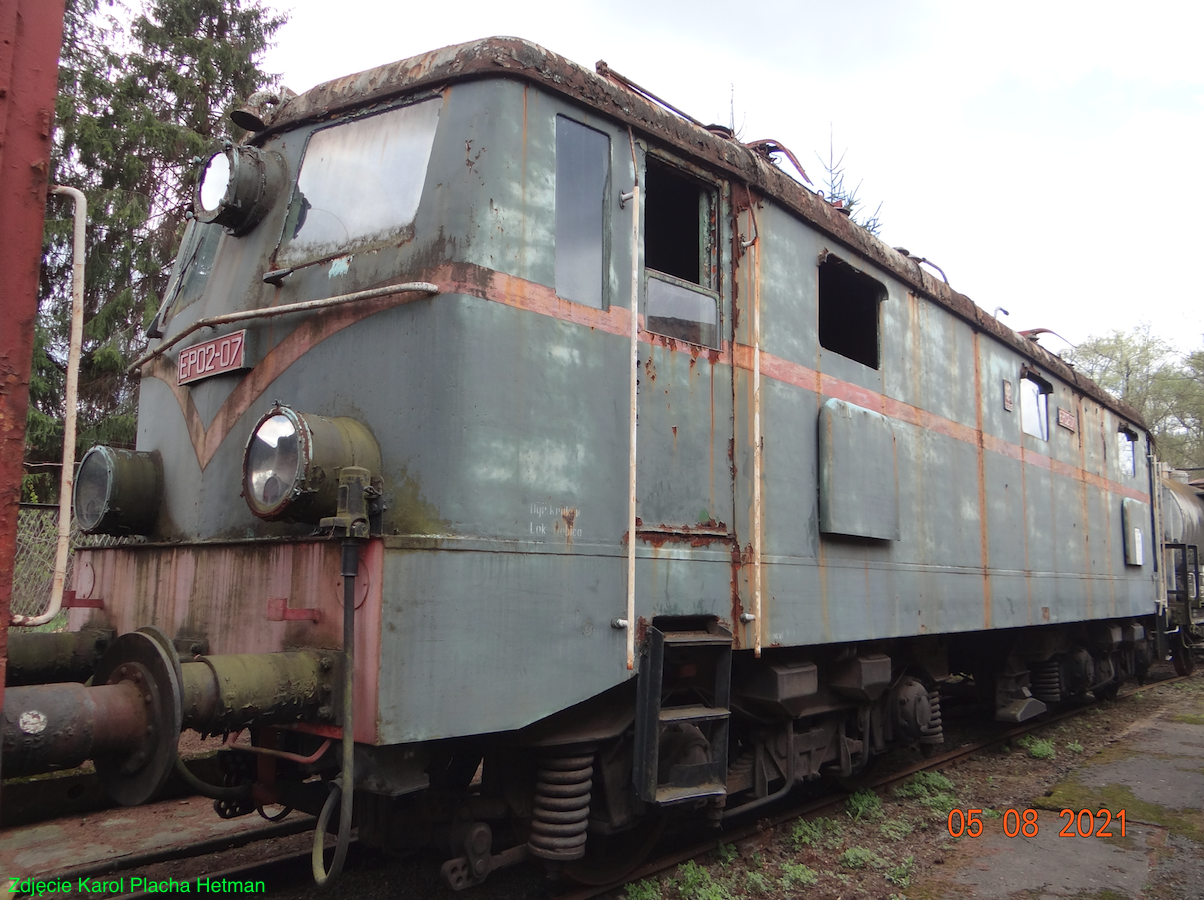
The EP02 series locomotives were relatively unreliable. Repairs took a long time because, among other things, parts from England had to be purchased in foreign currencies, and there were not many of them in Poland. In 1971, when the EP02 locomotives were replaced with newer designs, it was decided to carry out comprehensive tests, which were carried out by the Central Research and Development Center for Railway Technology. It turned out that at a speed of over 70 km/h, the locomotive had an unsettled run, it snaked, which was reported earlier by the drivers. There were also vertical vibrations. The sliding bearings of the wheels often overheated and there were melted bushings, which the designers had predicted, which is why the design included rolling bearings. The main cause of the bushing defect was the “economical” metal alloy with a low tin content. The High Voltage compartment also caused problems. However, the biggest defect of the EP02 was the frequent cracking of the wheel rims, which seriously endangered safety while driving. A new EP02 operating manual was written. As a result of the tests, it was decided to limit the maximum speed to 70 km/h. Many defects could not be eliminated, so it was decided to withdraw the locomotives from traffic. After being withdrawn from service on the routes, the Kraków Wagon Board became interested in the locomotives, which proposed that PKP transfer them to the stationary, electric wagon heating (SUG) at the Kraków Płaszów, Zakopane and Przemyśl stations. In August 1972, the electric locomotives were transferred to this work.
Currently (2021) three locomotives have been preserved: EP02-02 in Warsaw, EP02-07 in Chabówka, EP02-08 in the locomotive shed in Kraków Prokocim.
Design of EP02. The EP02 series locomotive has a typical design of an electric locomotive. The locomotive body, based on the frame, is mounted on two Bo’Bo’ type bogies. Four electric traction motors are used, one for each axle. The locomotive suspension is with two-stage springing, using leaf and coil springs. In theory, the bogies could move at a speed of 110 km/h, but the locomotive was approved for a speed of 100 km/h. The bogie was made of thick logs as a box with cutouts for the suspension of the axles of the wheel sets and with a rocker beam. Compared to the EP01 series, the axle spacing in the bogie was reduced. The axles of the wheel sets are suspended on leaf springs, and the springs on hangers. The wheel sets slide in the axle boxes of the bogie box. The wheel axles rotate in sliding bearings (shells), although the designers took care of the double-row rolling bearings.
In the locomotive from EP09-01 to EP09-07, English MV-185 R engines were used, with a total continuous power of 1,360 kW, with a 69:22 gear ratio. Traction engines of the MV185 R type, characterized by a large mass per unit of power, low rotational speed and a low degree of de-excitation.
In the locomotive EP02-08, “Dolmel” LKa-635 engines were used, with a total continuous power of 1,240 kW, with a 78:31 gear ratio. Dolmel engines were then used in the electric locomotive of the ET21 series.
The drive is transmitted via a single-sided gear. Since there were problems with obtaining rolling bearings, the wheel axles were suspended on sliding bearings, with a journal diameter of 175 mm. The wheel diameter is 1.22 m.
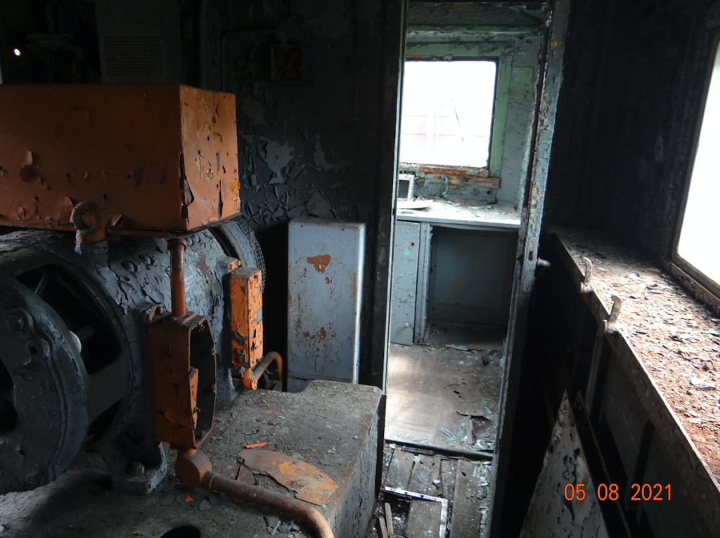
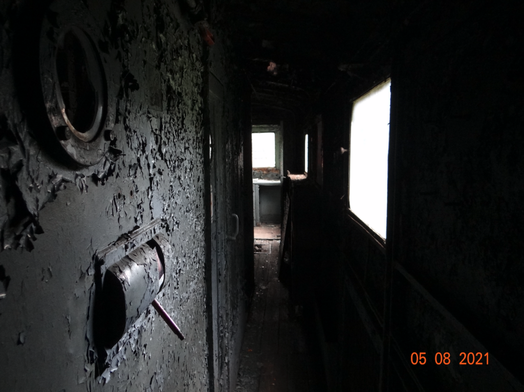
The frame and body are welded metal, and the interior finish of the cabins is made of wood and plywood. The body is supported on bogies via central pins and on four side slides. At both ends of the body are driver’s cabins, to which doors lead from the left and right sides. The doors have opening windows. In the front wall there are two windows, between which the upper reflector is placed. The front windows were to receive electric wipers, but due to the lack of electric motors, manually operated wipers were used. Each driver’s cabin has a door to the engine room.
The middle of the locomotive is occupied by the engine room. The corridor in the engine room runs along one of the sides. In the sides, on each side, there are three windows and two ventilation grilles. The engine room contains two fan systems for the traction engine cooling systems, two air tanks. There are compressors for the braking system, pantograph lifting and others. In the centre of the engine room there is a large high-voltage compartment, which is accessed through one door from the engine room corridor. In the electrical cabinet, on each side of it, there are starting resistance and fan and converter compartments. Two 3,000/110 V DC converters have been installed.
The electrical equipment is designed and manufactured by English Electric. It is structurally identical to that installed in pre-war EL100 locomotives. The locomotive is started by resistance. The main circuit was protected by a fuse, which was later replaced with a high-speed switch.
The locomotive was equipped with a Knorr-Bremse air braking system. Sandboxes were placed between the wheel sets. Two scissor-type pantographs (current collectors) were installed on the roof.
EP02 locomotive data: Manufacturer PaFaWag in Wrocław. Axle arrangement Bo’Bo’. Locomotive weight 81,000 kg. Wheel diameter 1.220 m. Length 15.00 m. Width 3.07 m. Height 4,511 m. Maximum speed 100 km/h. Power supply 3,000 V DC. Continuous power 1,352 kW. Engine speed: 870 rpm. Two compressors with a total capacity of 2,000 l/min. Traction power 169 kN. Axle load on rails 20,250 kg.
Written by Karol Placha Hetman