Kraków 2021-03-03
Electric traction in Poland in PKP.

3 000 V DC.
In 1932, a cross-city railway line was opened in Warsaw, which connected the western and eastern parts of our capital. Previously, it was necessary to detour trains through the Dworzec Gdański station, which is located in the northern part of Warsaw, using the so-called bypass line. The cross-city railway line partially runs in a tunnel. Tunnels for trains were nothing new. However, a steam locomotive causes a lot of smoke. According to the regulations at the time, one train pulled by a steam locomotive could pass through the tunnel every 30 minutes, so that the tunnel had time to air itself. Such a restriction negated the sense of this investment. A decision was made to electrify the Warsaw railway junction (WWK). By September 1939, it was possible to electrify about 149 km of railway lines, including a 40 km section of the EKD (Electric Commuter Railways) / WKD (Warsaw Commuter Railways) line Warsaw – Milanówek / Grodzisk Mazowiecki.
In the 1930s, many cities in Poland already had electric trams: Lviv (1894), Kraków (1901). Trams were powered by direct current, usually with a voltage of 600 V DC. Unfortunately. It was not possible to directly transfer solutions from trams to railways. A tram is a relatively light vehicle and covers distances of up to a dozen or so kilometers. Trains are much heavier and cover very long distances. In such a system, electrical substations should be every few kilometers. Raising the voltage to 1,500 V DC caused the power grid to be thicker and heavier. The poles had to be placed more densely. In cities, tram companies had their own power plants or contracts with municipal power plants. Railways had to be supplied with electricity from the national grid. Railway electrification with direct current of 1,500 V DC was introduced, for example, in France, Great Britain, Denmark and the Netherlands.
Initially, railway electrification worldwide was based exclusively on direct current, simply because there were no suitable alternating current motors at that time.
Direct or alternating current?
Which current is better? The discussion of arguments among engineers was very difficult. In the USA, it even led to the construction of an electric chair. Today, no one remembers what current was used to kill the first convict. But many remember that he was not killed, but fried.
The power industry professionally produces 50 Hz alternating current, because it is easier to transmit it over long distances. Currently, alternating current is easily converted to direct current using a transformer. At the turn of the 19th and 20th centuries, before the invention of semiconductors, this was a significant problem. In practice, rotating converters were used, i.e. a combination of a three-phase alternating current motor powered from the national grid with a direct current generator.
Alternating current was a good proposition. The traction network can be lighter, which guarantees higher voltage (V), lower current (A). As a result, substations can be set up every 40 – 60 km, much less often than with direct current.
Three-phase AC motor.
The most optimal type of AC motor is three-phase motor. They do not have a commutator. The disadvantage of these motors is a very high current consumption during start-up.
Historically, the first three-phase AC electric motors were very large and heavy. Only two such motors could be installed in an electric locomotive, at both ends of the electric locomotive. In order to transfer power to more driving axles, classic trusses from steam locomotives were used. The problem was supplying three phases to the locomotive. Three phases means three wires. The Germans experimentally used traction of three wires next to the tracks at different heights and three current collectors. This complicated the construction of the traction network. Despite this, as early as 1899, an experimental line with three-phase traction was built in Germany. On this line in 1903, the tested train reportedly reached a speed of 210 km/h. Despite this, the system was so complicated that the Germans abandoned further experiments and began to promote the single-phase system.
In the 1920s, the Italians began electrifying their railways in a three-phase system. Their idea was to place two wires on top, which were touched by a pantograph with two shoes. The third wire was the rails. In practice, however, this system also caused many problems. Three-phase motors draw a large current when starting, which meant that the network had to be heavy, and substations supplying power more often than in a single-phase system. However, the substations were of simple construction and had only a transformer.
In the 1930s, the Italians were the leaders in electrification. They had the most electrified lines of any country in the world; 5,170 km, which was 22% of all Italian railway routes. The Italians tried to export their three-phase technology, offering it, for example, to PKP and the cross-city line. But the costs of servicing and repair were high. As a result, in the 1950s, the Italians changed the electrification system to 3,000 V DC, such as in Poland.
Single-phase AC motor.
In practice, it was not possible to build a good high-power single-phase AC electric motor. At a frequency of 50 Hz, there were significant problems with commutation; switching the windings in the motor. An effective solution was to reduce the frequency of the supply network to 25 Hz, or even to 16 2/3 Hz. However, other problems appeared at that time. Transformers with a reduced frequency must be larger and heavier. There were problems with the imperfection of the then electric motor with a commutator. A major challenge was changing the frequency from the industrial 50 Hz to a lower one, with a frequency of 16 2/3 Hz or at most 25 Hz. This change in frequency was associated with high costs of electrical – power equipment.
Electrification of railways with alternating current of 15 kV 16 2/3 Hz was implemented and was used in Germany, Austria, Switzerland, Norway and Sweden. Electrified routes in the Sudetes in Germany (1930s) had their own power plants. In the Sudetes there were about 400 km of electrified routes, which in 1945, the Soviets dismantled and took to Moscow. When stealing infrastructure, the Muscovites said that the poles were going to galvanization.
Single-phase DC motor.
A commutator is present in a DC motor and its task is to change the direction of current flow through the frame. Commutators are the weakest element in a DC motor. However, technical and material progress has caused DC motors to operate without failure for decades. As a result, all electric locomotives in the world have DC motors. Diesel locomotives, which have an electric transmission, also have such motors; diesel engine – generator – electric motor. Such a system was once called a three-machine.
Electrical energy 25 kV 50 Hz.
A few years before the Second World War, the Germans undertook tests using alternating current for railway traction, with a normal frequency (50 Hz). They advanced the work so far that they launched a small section of the railway line in the Black Forest. They built four different electric locomotives and began testing them. They did not complete the tests because the war broke out. After the war, France continued these tests and concluded that it had advantages. They decided to build their railways based on 25 kV 50 Hz alternating current. In addition, it was possible to change the already built 1,500 V DC traction to 25 kV 50 Hz. During the tests, the French used their own locomotives and their own test section in Haute-Savoie.
In the 1950s, the concept of single-phase alternating current power supply with an industrial frequency of 50 Hz and a voltage of 25 kV was returned. This time, it was planned to use well-mastered direct current motors in electric locomotives, and in addition to the transformer, the locomotive had a mercury rectifier on board. This system developed significantly in the 1960s with the development of semiconductor technologies. Silicon rectifiers and inverters were used. Currently, more and more railway lines in the world are electrified using this system. The cost of construction and operation is the lowest. The traction network is light and there is a large distance between substations, which are of simple construction. Among others, the French TGV high-speed railways are built using this system.
Direct current in Poland.
In the 1920s, mercury rectifiers were developed, which eliminated the need to build special power plants or use troublesome and inefficient rotating converters. Locomotives also did not have to carry large and heavy transformers, which was especially important when using the so-called ETZ – Electric Traction Units, to service suburban traffic. Electric suburban railways gained great popularity.
As a result, for example in Germany, two different railway systems were created. The suburban railways for Berlin have a direct current of 800 V DC.
In Poland, after a discussion between professors and engineers, it was decided to electrify with a direct current of 3 kV DC. At that time, such a fragmented network was installed in the USA on a section of 700 km, between Chicago and St. Paul. The operational results confirmed the great technical advantages of this solution. Poland followed the systems used in England, where 1,500 V DC was used, but decided on a higher voltage of 3,000 V DC.
In Poland, in 1928, it was assumed that the cross-city line would be electrified by November 1931. However, the global crisis caused the first stage of electrification to be completed in 1936. Initially, it was assumed that electric traction would be built between the Warszawa Wschodnia and Warszawa Zachodnia stations, in order to pull classic trains between them. However, it was decided to extend the scope of work to Żyrardów, Otwock and Mińsk Mazowiecki, in order to service local traffic using EZT trains. A total of 106 km of lines. The contract for electrification was concluded with two English companies: The English Electric Company and Metropolitan Vickers Electric Company. Part of the rolling stock was to come from Poland. Among others, 76 EZT sets, the production of which was undertaken by the Lilpop, Ran and Loewenstein plants in Warsaw, H. Cegielski – Poznań and Zieleniewski, Fitzner – Gamper in Sanok.
On 15 December 1936, the ceremonial launch of electric trains on the section to Pruszków took place, and a year later, on 15 December 1937, trains were already reaching Mińsk Mazowiecki.
Individual electric locomotives were remembered for pulling regular trains. Two EL100 series locomotives manufactured by Metropolitan Vickers were delivered from Great Britain. Based on the license and documentation as well as electrical equipment, four more EL100 electric locomotives were built in FabLok in Chrzanów. After World War II, only one locomotive returned to service, which received the designation EP01. In 1968, it was scrapped. In addition to these six heavy electric locomotives, four light EL200 locomotives were also built in 1937, in the HCP plant, from the same electrical components as the EZT trains being built. Unfortunately, none of them survived.
Post-war electrification in PKP.
The period of World War II completely destroyed the electric traction equipment of WWK (Warsaw Railway Junction). A large part was also taken away by the occupiers, mainly passenger rolling stock and locomotives. The reconstruction of the traction network began on January 25, 1945. The electric locomotive shed at Grochów station and at Warszawa Wschodnia station were rebuilt. Traffic was gradually restored. On September 14, 1948, electric trains returned to the Warszawa Wschodnia – Mińsk Mazowiecki route: electric locomotives and EZTs. Decisions were made to electrify the main railway lines of the country.
The first rebuilt, electrified route was the Warszawa Wschodnia – Otwock section. The first test train ran along this route on July 14, 1946. In April 1947, agreements were concluded with Sweden for the supply of electrical components for the railways, as well as electric multiple unit and locomotives. In 1948, the renovation and electrification of the Warsaw – Katowice route began. Many stations on the route had to be rebuilt. The plan also included the electrification of the Koluszki – Łódź branch line and the Wejherowo – Pruszcz line. On June 3, 1956, an electrified route from Warsaw to Łazy near Zawiercie was put into service, with a total length of 281 km. The route led through: Skierniewice – Koluszki – Piotrków Trybunalski – Częstochowa – Zawiercie. In 1957, electric trains were already reaching Katowice and Gliwice. In 1959, the Śląsk – Kraków route was electrified, through: Szczakowa – Trzebinia – Kraków – Nowa Huta. In 1964, the Kraków – Rzeszów route was electrified. In 1961, Poland already had about 1,200 km of electrified routes. This was 25% of the then assumptions.
At that time, the discussion about the type of electric traction began again. After a substantive discussion, it was decided to stick with the pre-war 3 kV DC system. Reconstruction to 25 kV 50 Hz current was then an economic nonsense. The contribution of the pre-war pioneers of PKP electrification, who carried out a lot of study and development work, also in the field of nomenclature and technical regulations, was appreciated.
Mercury rectifier.
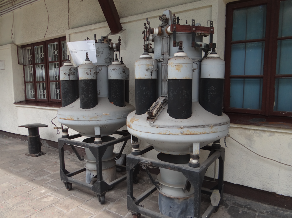
A mercury rectifier, also called an ignitron, is also called a Hewitt rectifier. A rectifier is an element or set of electronic elements used to convert alternating voltage to a single-sign voltage, which after further filtering can be changed to direct voltage.
These rectifiers were used in all devices requiring high power from several kilowatts to several megawatts. Operating voltages ranged from 110 V to 30 kV. The method of operation is based on the discovery that an electric arc between liquid mercury (cathode) and a metal electrode (anode) allows current to flow in one direction. They usually had several anodes powered by a multi-phase transformer, where the electric arc jumped from the cathode (mercury pool) to individual anodes. This allowed for more precise and continuous operation of the rectifier. Six-phase and even twelve-phase systems were often used using star-connected three-phase transformers with interphase transformers at the connections.
The use of electrical energy of 3 kV DC to drive electric locomotives and EMUs will allow an AC to DC rectifier in the form of a mercury rectifier. A mercury rectifier is generally a glass bulb in which about 1 liter of mercury is located. The mercury is on the cathode electrode side. The mercury rectifier is made as a vacuum or gas lamp (inert gas). The rectifier has an additional ignition electrode called an ignitor, which is why the rectifier is called such.
The mercury rectifier was the basic device installed in PKP traction substations. These were often mercury rectifiers manufactured by the EAW factory in the GDR. The rectifier had a vacuum inside and could not be dismantled. This made it easier to service and reduced the number of parts that could be damaged. Two such devices operated in one unit, connected in parallel. Three-phase alternating current from the 110 kV network reached the substation. On the other side, direct voltage of up to 3,300 V DC and current of 330 A (from one mercury rectifier) came out. In total, six phases came out, which were distributed to various traction sections by cables. The mercury rectifier had safeguards. This rectifier required a very stable anode temperature and was therefore either heated or cooled. The disadvantage of mercury rectifiers is the mercury itself. There was a fear of emitting small mercury vapors into the environment.
This was a time when semiconductors were not yet used. In the following years, the glass bulb was replaced by a box made of special metal alloys, and its walls were the cooler of the mercury rectifier. Currently, mercury rectifiers are no longer used in industry. They have been completely replaced by cheaper, more efficient and smaller semiconductor rectifiers, silicon diodes. Semiconductor technology made it possible to produce silicon rectifiers. The simplicity and durability of their construction allowed them to be placed in the box of an electric locomotive.
Discussion on the electrification of PKP in 1956.
The discussion about which current; direct current or alternating current, began once again around 1956. Opinions were divided. Supporters of single-phase alternating current even used the argument that PKP was opposed to technical progress. Nevertheless, PKP’s decision was preceded by long-term and comprehensive research and calculations, opinions of scientific institutions and professional scientific and technical associations NOT. The results and opinions were unambiguous and unanimous; It is not profitable to introduce alternating current to Polish railway lines. The discussion started again after 2015 did not change the conclusion. For the railways, the matter is completely clear; We remain at 3 kV DC.
The voltage level determines the cross-section of the wires. The higher the voltage, the smaller the cross-section. It must be remembered that 100 m of copper wire, with a cross-section of 100 mm2, weighs about 1 ton. In Poland, we used and still use two 250 mm2 contact wires. But in France, when it used a voltage of 1,500 V, the cross-sections of the wires were as much as 800 mm2. It is easy to calculate how many tons of copper had to be suspended in the air and how dense the traction poles were.
In the 40s of the 20th century, engineers around the world worked intensively on a single-phase AC motor that could work at the industrial frequency of 50 Hz. At that time, the problem was not solved in a satisfactory way.
A few years before the Second World War, the Germans undertook tests using AC for railway traction, with a normal frequency (50 Hz), to such an extent that they launched a small section of the railway line in the Black Forest. They built four different electric locomotives and began testing them. They did not complete the tests because the war broke out. After the war, France continued these tests and as a result concluded that it had advantages. They decided to build their railways based on 25 kV 50 Hz alternating current. In addition, it was possible to change the already built 1,500 V DC traction to 25 kV 50 Hz. During the tests, the French used their own locomotives and their own test section in Haute-Savoie.
In 1953, France decided to electrify exclusively with alternating current. From that moment on, the trend of electrification with single-phase alternating current dates back.
In other countries, different decisions were made. Countries that were at the beginning of electrification decided on alternating current. Countries that already had partial electrification remained with direct current: Belgium, Italy, Poland. Poland was justified by the fact that it had mastered 3 kV DC technology and lacked 25 kV 50 Hz technology. The English went the furthest, even rebuilding some sections already electrified with 1,500 V DC direct current to high-voltage alternating current traction. Of course, this caused disputes among specialists, the echo of which continues to this day (2021).
However, the problem has not been completely solved. Alternating current is not cost-effective in all conditions. It is economical on long sections and on routes with high traffic. Then you can assemble freight trains weighing 3,000-4,000 tons. But such a train is very long and will not fit on a side track at every station. Alternating current is not suitable for local EZT trains, because there is no room for a large and heavy transformer. In 1960, Polish engineers conducted a simulation of the Poznań-Szczecin route with 25 kV 50 Hz current. (Comparative study of the electrification of the Poznań-Szczecin line with 3 kV direct current and 25 kV 50 Hz alternating current. May 1961). With alternating current, the investment cost would be lower by 5-7%. Operating costs would also be lower, by about 10%. Electrification of only part of the routes would be anachronistic. There would have to be different locomotives. There would be no reduction in travel time.
In addition, a new power grid would be necessary. The 110 kV grid is too weak. A 220 kV or even 400 kV grid would be adequate, and there were and are few such grids in Poland.
The studies carried out have shown that in the current conditions, despite some savings on power supply equipment, the total expenditure on electrification and accompanying works for the new system would be greater than the corresponding expenditure related to electrification with a direct current system.
In the 1960s, there was a problem for the rolling stock industry, and especially the PaFaWag factory, which built electric locomotives. For them, the foreign market, where there was 25 kV 50 Hz, was closed. It was planned to build a test track for this type of electric locomotives, which was not done. Only in 2017, such a test track was built by NEWAG near Nowy Sącz.
In 1965, the discussion was ended by the Ministry of Communications, issuing a regulation on the continuation of electrification with 3 kV DC. In Poland, the discussion was resumed in the mid-1980s. However, the Polish economy was in a major crisis and the discussion was only on paper.
The planned Central Communication Port once again sparked a discussion: 3 kV DC or 25 kV 50 Hz. Another report appeared entitled “3 or 25 kV?” This was another substantive discussion. The results obtained showed that it is not possible to clearly state which of the traction power supply systems is better in Polish conditions. Especially when we are talking about passenger trains with a running speed of 200 – 250 km/h.
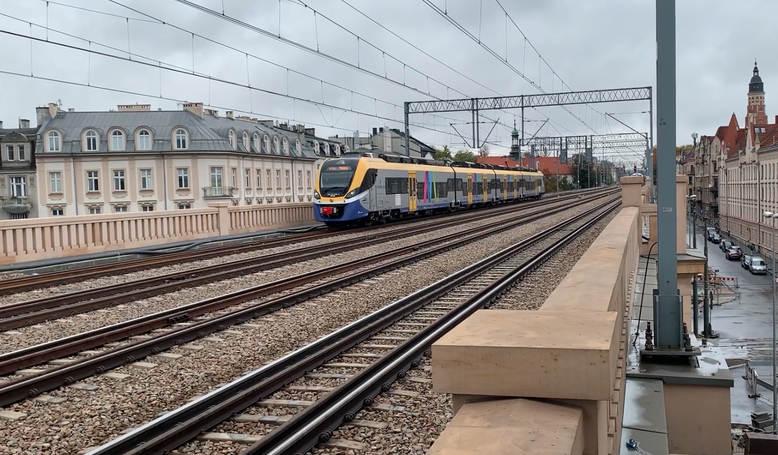
In 2020, there are about 12,000 km of railway lines electrified in the 3 kV DC system in Poland. This is about 60% of all railway lines in Poland. These are mainly lines of national and transit importance. They are powered by over 500 traction substations, largely new or modernized in recent years.
25 kV 50 Hz AC system currently. 2020.
In the block diagram, both systems are similar: 3 kV DC and 25 kV AC. The traction power flow sequence is as follows: AC supply line – step-down transformer – rectifier – voltage regulator – DC traction motors. Even in the AC system, DC series motors are used, because their traction characteristics best correspond to the required operating conditions in an electric and diesel locomotive with an electric transmission.
The difference is the different location of the contact point between the traction network and the current receiver (pantograph) in this sequence. In the DC system (direct current), the step-down transformer and rectifier are located in the traction substation building. As a result, the pantograph (current collector) is the weakest link in the system. Therefore, in the 3 kV DC system, there are two traction wires, not because of the wire (conductor) cross-section, but because of the largest possible contact surface between the collector and the wires.
The 25 kV AC system has less frequently spaced substations, every 50 – 60 km, much less frequently than in the case of 3 kV DC (every 15 – 25 km). Thinner traction wires mean a lighter network and less frequently erected traction poles. There is only one contact wire. Higher voltage means lower amperage, and as a result, smaller voltage drops along the traction network, and therefore smaller energy transmission losses.
The disadvantage of the 25 kV 50 Hz system is the high requirements for the public power supply network. One phase loads the supply network more and asymmetrically. Therefore, a 220 kV or even 400 kV line is preferred. A 110 kV network can be used, but requires the use of additional devices that will reduce phase asymmetry. In addition, 25 kV 50 Hz interferes with devices used in PKP, such as SRK. Axle counters are already used on modernized railway lines, which are insensitive to return and stray traction currents, but a whole range of sensors and controllers operate at the industrial frequency of 50 Hz. The 3 kV DC system does not have these disadvantages.
Many years of operation have shown that there is no problem with transmitting energy through the pantograph up to a train speed of 200 km/h. The problem occurs at speeds over 250 km/h. In Italy, a fast train runs at a planned speed of 220 km/h. In Poland, the Pendolino runs at 200 km/h and a little more.
At 3 kV DC, however, the construction of the electric locomotive itself is simpler, and therefore the cost of purchasing rolling stock to service specific trains is lower.
Technological progress has made it possible to send energy through high-voltage traction network cables, while its reduction and rectification took place in the locomotive itself. However, the problem was the step-down transformer, the dimensions of which did not allow it to be placed under the vehicle body or on its roof. Therefore, EZT designs were not developed on AC railways. As a half-measure, variable-direction trains were developed, also known in Poland today as “push-pull”.
Current technology enables the construction of multi-system locomotives. Such locomotives are built in Poland. The cost of a multi-system locomotive is not as drastically higher than a vehicle with a single power supply system, as it was in the 20th century. All that is needed is a safety system so that the wrong pantograph is not raised to the wrong network.
In Polish conditions, the standard is 440 mm2, i.e. two 220 mm2 conductors. There were economically important railway sections where two 250 mm2 conductors were installed. For example, in Italy on the Rome-Florence route, there are 620 mm2. Here, trains run at a speed of 220-250 km/h. In Polish conditions, the nominal speed is 220 km/h.
The current discussion is moot, because billions of zlotys have already been spent on modernizing the railway infrastructure. Many routes have already been adapted to passenger train speeds of up to 160 km/h.
Polish railways have electric locomotives that can already run at a speed of 200 km/h. Polish new EZTs run at 160 km/h as standard. Similarly, classic trains already reach 160 km/h. Many electric locomotives already have asynchronous electric motors, which have better parameters. New SZT trains normally travel at speeds of up to 120 km/h. This results from the physics of the electric transmission used in these trains and economics.
What was planned for the electrification of 25 kV AC in PKP?
The Central Railway Trunk Line was selected for changing the current to 25 kV AC. However, the undertaking is uneconomical.
The newly built “Y” route Warsaw – Łódź with a branch to Poznań and Wrocław was selected. The route has not been built yet.
The route No. 203 Kostrzyn nad Odrą – Gorzów Wielkopolski – Krzyż Wielkopolski – Piła – Chojnice – Tczew was selected. Here, problems were encountered with the crossing of the 25 kV 50 Hz route with the 3 kV DC network at the stations: Kostrzyn (here there is a smaller problem, because the main routes cross on the railway viaduct), Krzyż Wielkopolski, Piła, Tczew.
In 2010, the Management Board of PLK S.A. decided to prepare the planned section of the “Rail Baltica” line from the Ełk station through Suwałki to the border in Trakiszki, treating this section as a testing ground. From an economic point of view, only the electrification of the LHS line with 25 kV 50 Hz current makes sense. This broad-gauge railway network is independent of the standard gauge. All the more so because there is a 400 kV power grid nearby.
Written by Karol Placha Hetman